



業界ニュース


閲覧: 6

発表時間:2026-09-10
A flexible LED module may be used on a small cylindrical display in one project and on a wide curved wall in another. Sometimes the module model, pixel pitch, and size are exactly the same, but the finished curves look completely different.
This often creates a question:
If the LED module is the same, why is the bending radius different?
The reason is simple. A flexible LED module normally does not have one fixed working
radius. It has a safe bending range. Within that range, the supporting frame controls much of the final geometry.
In other words, the module provides flexibility. The frame gives that flexibility a shape.
This is the first point to understand.
When a flexible LED module specification gives a minimum bending radius, it describes a mechanical limit rather than the only radius the module can use.
For example, imagine a module that can safely bend to a minimum radius of R300 mm.
That does not mean every screen using this module must be R300.
The same module might be installed on:
an R400 frame for a tight curve;
an R800 frame for a moderate curve;
an R1500 frame for a gentle curve;
or a much larger radius that looks almost flat.
The exact allowable range depends on the module design, PCB, mask, components and bending direction.
This is why the LED module bending radius and the finished curved LED display radius should not be treated as the same specification.
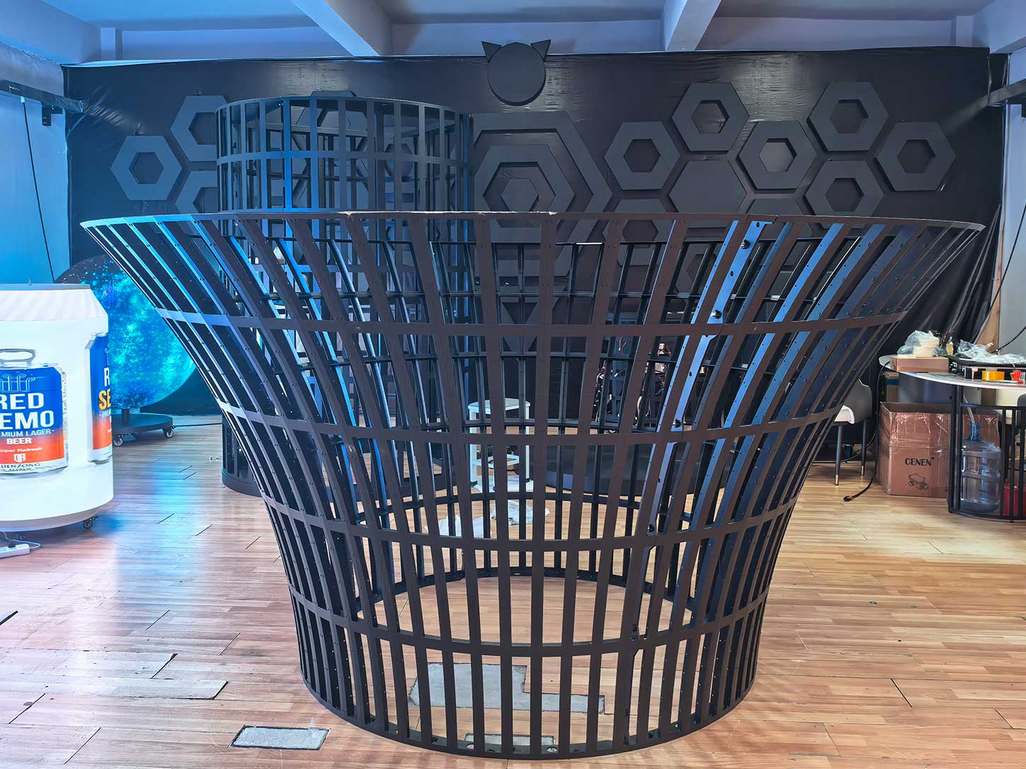
A flexible module does not normally hold an accurate architectural curve by itself.
During installation, the back of the module is attached to a steel or aluminum supporting structure. Magnetic mounting is commonly used because technicians can position and remove modules from the front.
Once the magnets contact the structure, the module begins following the geometry underneath it.
If the frame is R500, the module is pulled toward an R500 surface. Put the same module onto a larger-radius structure, and it becomes much flatter.
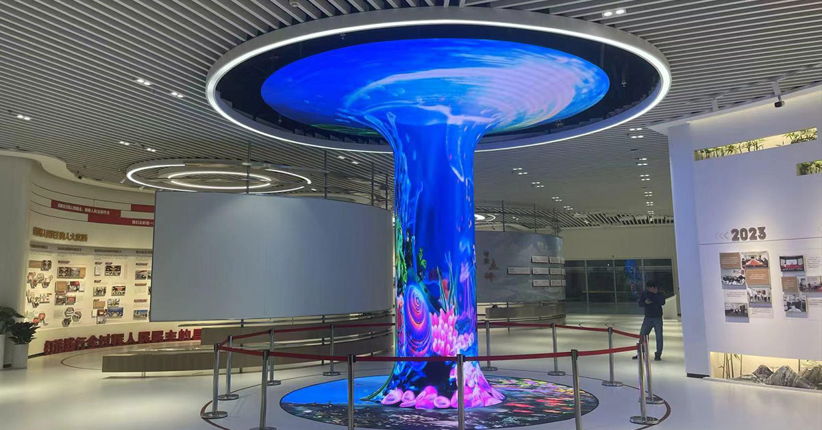
This principle is used in curved walls, columns, cylinders, waves and many other custom-shaped LED projects.
For this reason, the supporting structure should be designed together with the LED system rather than treated as a simple frame added at the end.
Frame radius alone does not tell the whole story.
Consider a flexible LED module attached to a curved structure at many evenly spaced points. Each point helps pull the module toward the intended curve. The display surface can follow the frame closely.
Now imagine the same module supported at only a few points.
The area between two supports may not perfectly follow the designed arc. A small section can become flatter or slightly raised.
This can create:
uneven module joints;
visible local flat spots;
inconsistent gaps;
reflections that change along the curve;
small differences in the apparent radius.
Therefore, engineers need to consider not only where the frame goes, but also where the module actually contacts the frame.
Magnet position, support spacing and module size all influence the final surface.
This is especially important for large custom LED structures.
Some curved frames are manufactured from multiple short metal sections. Instead of producing one continuous arc, the manufacturer creates many small segments that approximate a circle.
The shorter and more accurately positioned those segments are, the smoother the finished curve can become.
If the segments are too long, the LED surface may develop slight flat areas. From a distance, the display still appears curved. At close viewing distances, however, the surface can look slightly polygonal.
This is one reason two structures designed with the same nominal radius may not produce exactly the same result.
The drawing may say R1000.
The actual LED surface depends on how accurately that R1000 geometry was manufactured.
Suppose two projects both specify an R500 curved frame and use exactly the same flexible LED modules.
The finished displays can still look different.
Possible causes include frame cutting accuracy, welding deformation, module positioning, magnet height, installation pressure and structural tolerances.
Even a small local deviation can affect several neighboring modules.
For example, if one part of the steel structure sits slightly higher than the surrounding area, the module may not fully contact the intended curve. The neighboring modules then have to compensate for the difference.
The result may appear as a wider seam, a small raised area or a change in surface reflection.
This is why simply checking the radius number on a CAD drawing is not enough.
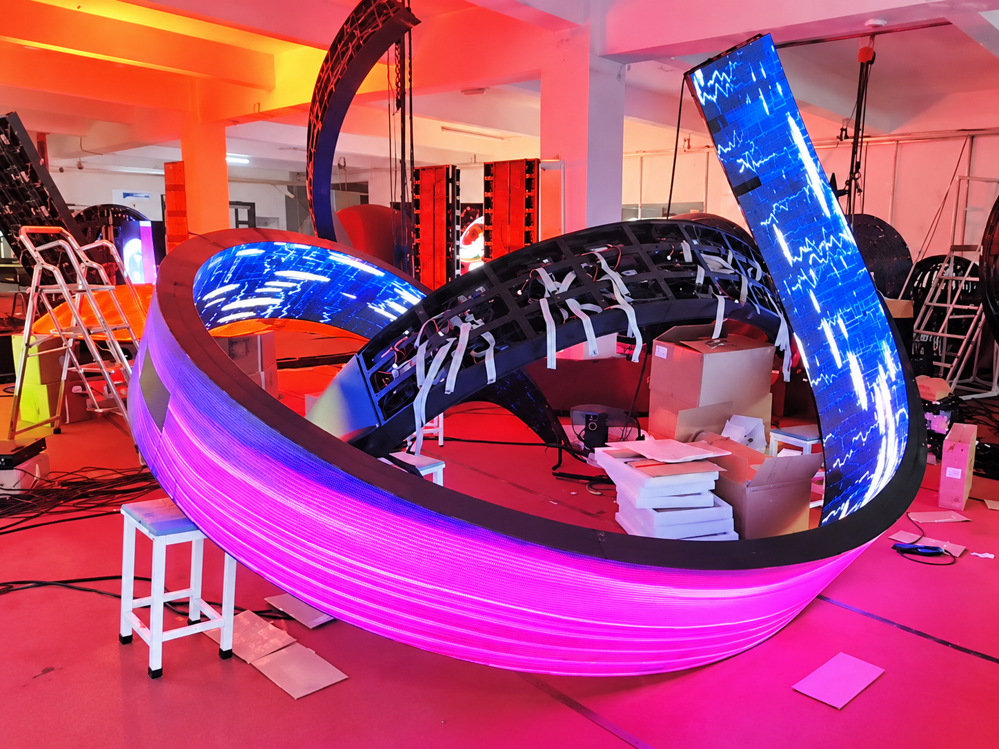
A better approach is to verify the structure before hundreds of modules are installed.
The process can start with the CAD drawing, but physical inspection is equally important.
Engineers can check several dimensions across the structure and compare them with the design. For circular sections, chord and sagitta measurements can help confirm whether the manufactured curve matches the intended radius.
The frame should also be checked for local deformation after welding and assembly.
After that, several real LED modules can be installed as a trial section.
This small test can reveal problems that are difficult to see on an empty steel frame:
Does every magnet contact the structure?
Do neighboring modules remain level?
Are the seams consistent?
Does the surface form a smooth continuous curve?
Finding a 2–3 mm structural error at this stage is much easier than correcting it after the entire curved LED screen has been assembled.
Flexibility has a limit.
A frame should never force a module beyond its specified safe bending range.
Excessive bending can place unnecessary stress on the flexible PCB, connectors, solder joints, masks and other components. It can also cause the module edges to lift away from the supporting structure.
A tighter radius therefore does not automatically mean a better creative design.
Before production, the required diameter or radius should be compared with the mechanical capability of the selected flexible LED display.
If the requested curve is outside the safe range, engineers may need to change the module, modify the frame radius or redesign that part of the display.
Imagine a retail project using the same flexible LED module in three areas.
The first display wraps around a narrow column. It requires a relatively tight supporting frame.
The second display follows a large curved entrance wall. Its radius is much larger, so the same modules bend only slightly.
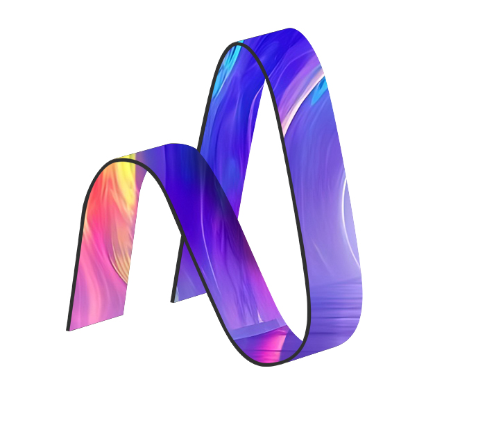
The third installation uses an S-shaped structure. Some sections have a tight curve while others gradually become flatter.
The LED module has not changed.
What changes is the geometry underneath it.
This flexibility is one reason curved modules are useful for architectural LED projects. Manufacturers do not necessarily need a completely different module for every diameter. A properly selected module can work across several designs, as long as every section stays within its permitted bending range.
Yes. A flexible LED module can normally work with different curved structures as long as the required radius remains within its safe bending range. The frame determines much of the final installed geometry.
Not by itself. Pixel pitch affects resolution and viewing distance, but bending capability also depends on the flexible PCB, module construction, component arrangement, mask design and module dimensions.
The radius of a curved LED display is not determined by the flexible module alone.
The module determines how far it can safely bend.
The frame determines where it actually bends.
Support spacing, magnet position, frame segmentation, fabrication tolerance and installation accuracy then determine how closely the finished LED surface follows the designed curve.
This explains why exactly the same curved LED module can produce very different radii on different projects.
Toosen LED provides flexible and custom-shaped LED display solutions for projects such as curved walls, columns, cylinders and other non-standard structures, with engineering support available for matching module type, pixel pitch and frame geometry to the required shape.
 +86 18688923792
  andy@tosled.com


