






News
Most genuine customer feedback, highly informative technical support videos, and our latest updates!

Most genuine customer feedback, highly informative technical support videos, and our latest updates!

View: 12

Release time:2026-09-15
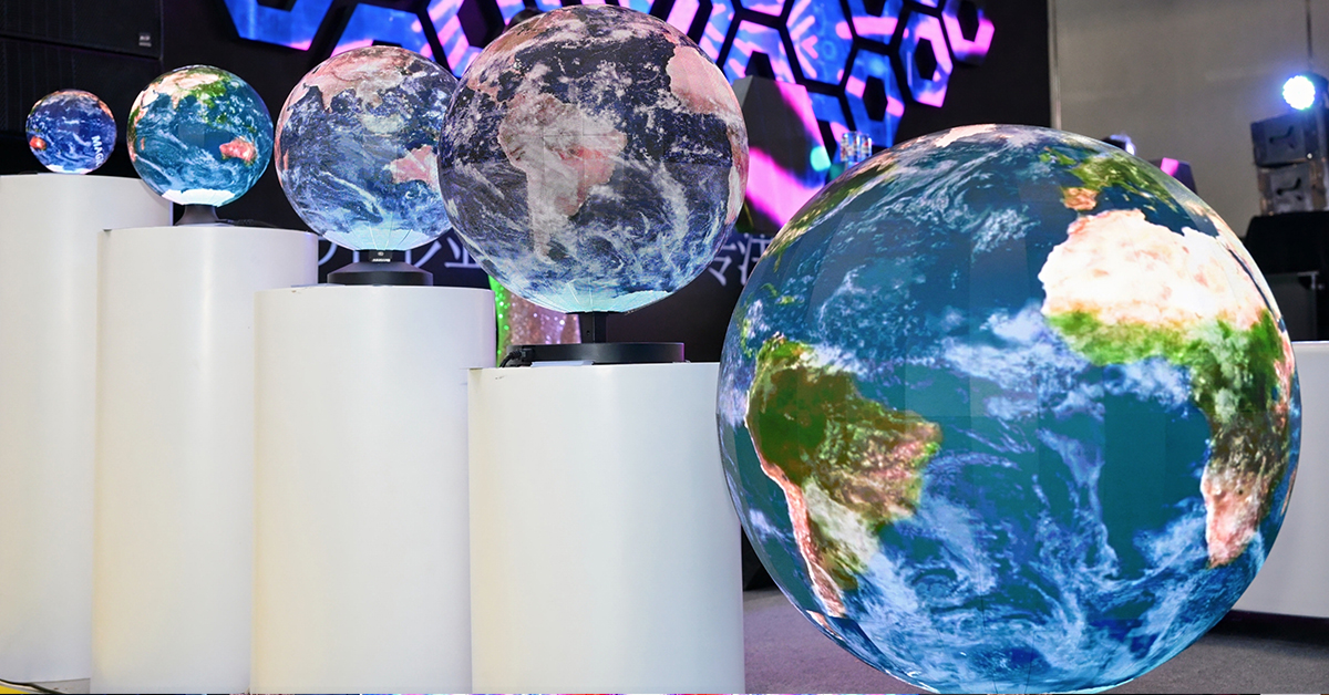
A large spherical LED display may contain hundreds or even thousands of LED modules. During factory assembly, engineers usually know where every module belongs. The real problem begins when the sphere is disassembled, packed, shipped and rebuilt at the project site.
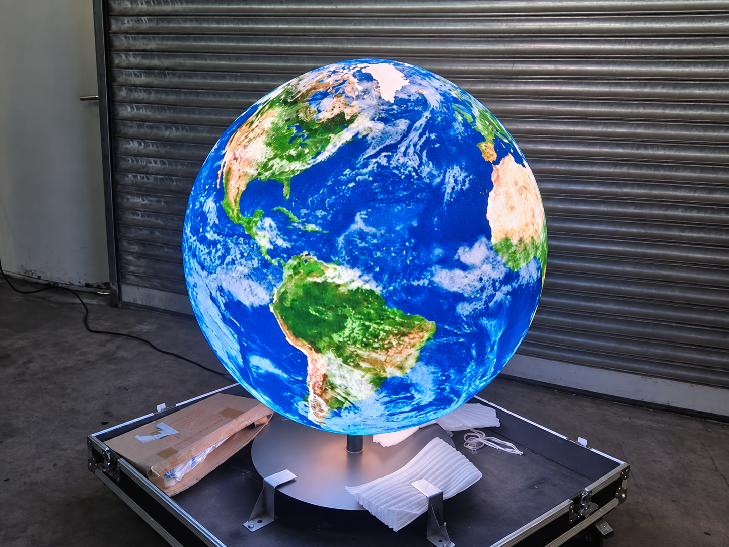
If the modules are only marked as No. 1, No. 2, No. 3 and so on, the installation team may still have difficulty finding their exact positions.
The same problem becomes more serious during maintenance. A customer may report that “one module on the right side is flickering,” but that description does not tell the engineer which module, receiving card, signal cable or power supply should be checked.
A good LED module numbering system solves this problem before installation begins.
A flat LED wall normally has a clear top, bottom, left and right side. Modules can therefore be identified with simple row and column numbers.
A sphere is different.
The modules wrap around a 360-degree surface. Some are near the top, some are around the equator, and others form the lower part of the sphere. Different rings may also contain different quantities or shapes of modules.
For this reason, numbering modules from 001 to 300 does not give enough physical information.
If Module 176 develops a problem six months later, a technician still needs to know:
Where is Module 176 on the sphere?
Which receiving card controls it?
Which network port carries its signal?
Which power supply feeds that area?
Which spare module should replace it?
The numbering system should answer these questions quickly.
Before numbering any modules, choose one permanent reference direction.
For example, the side facing the main audience can be defined as 0°.
Then define the other directions:
0° – Front
90° – Right
180° – Rear
270° – Left
The installation drawing, steel structure and control diagram should all use the same orientation.
It is also important to define whether module positions are counted clockwise or counterclockwise. Once the rule is chosen, it should not change during production, installation or maintenance.
Without this reference point, two technicians may give the same physical module two different numbers.
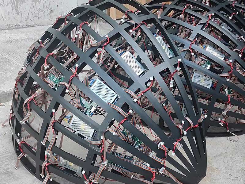
Instead of treating the entire sphere as one long sequence, divide it into logical areas.
One practical method is:
North / South + Ring + Module Position
For example:
N-R04-M12
This can mean:
N – Northern half of the sphere
R04 – Fourth horizontal ring from the top
M12 – Twelfth module in that ring
A module below the equator may be identified as:
S-R03-M08
This format immediately tells the technician approximately where the module is located.
For some custom spherical LED display structures, the sphere may be divided vertically rather than horizontally. In that case, another format can be used:
Segment 04 – Level 06 – Module 02
The exact code is less important than consistency. Every engineer, installer and maintenance technician must understand the same system.
One common mistake is using the receiving card number as the module number.
They are not the same thing.
A spherical LED screen may contain several different identification systems:
Physical Module ID: N-R04-M12
Receiving Card: RC-07
Ethernet Port: P03
Cable Order: #06
Power Supply: PSU-04
These numbers should be connected in a project record, but they should not replace each other.
A simple maintenance table can look like this:
| Physical Module ID | Receiving Card | Port | Cable Order | Power Supply |
|---|---|---|---|---|
| N-R04-M10 | RC-07 | P03 | #04 | PSU-04 |
| N-R04-M11 | RC-07 | P03 | #05 | PSU-04 |
| N-R04-M12 | RC-07 | P03 | #06 | PSU-04 |
If N-R04-M12 becomes black, the engineer immediately knows which signal and power area to inspect.
This is especially useful for a custom-shaped LED display because internal components may be located behind different structural sections. Planning component locations before installation also makes future access easier.
A numbering system is useful only if the number can still be found after the display has been installed.
For each module, the same ID should appear in several places:
On the back of the LED module
On the matching position of the metal structure
On the installation drawing
In the digital wiring and maintenance record
This creates a simple double-check system.
If a technician removes Module N-R05-M09, the label on the frame still shows where that module belongs.
Water-resistant printed labels, engraved tags or QR codes can also be used depending on whether the spherical LED display is installed indoors or outdoors.
The numbering system should be verified during factory assembly, not after the screen reaches the customer.
After the sphere is fully assembled, engineers can display a numbered test pattern on the screen and compare it with the physical labels.
The team should check:
whether the 0° direction is correct;
whether every ring starts at the correct point;
whether numbering follows the same direction;
whether the physical module matches the receiving card map;
whether the cable order follows the control diagram.
Photos of the front, rear and different angles of the completed sphere should also be saved with the project documents.
This gives the installation team a visual reference when rebuilding the screen on site.
Imagine that a customer reports:
“N-R06-M14 is flickering.”
The engineer can check the project record and find:
Receiving Card RC-09 → Port P04 → PSU-06 → Module Type T2
Before opening the screen, the technician already knows the approximate position, the control path and which spare part may be required.
This is much faster than inspecting the entire sphere module by module.
A clear numbering system also reduces the chance of installing the correct module in the wrong position after repair.
No. The numbering format should match the mechanical structure. A small sphere may use ring-based numbering, while a large custom sphere may need zone, segment and level codes.
No. Receiving card coordinates describe the control system. Module IDs describe physical positions. They should be linked but kept separate.
It should be created during the engineering and production stage, before full factory assembly.
Module numbering may look like a minor production detail, but it becomes valuable during every later stage of a spherical LED display project.
A clear system helps installers rebuild the sphere in the correct order, helps engineers verify receiving card and cable mapping, and gives maintenance teams an exact location when a problem appears.
For custom sphere projects, Toosen plans the LED modules, internal structure, control components and maintenance access according to the actual screen size and installation method. Building the identification system into the project from the factory stage makes installation and long-term maintenance much easier.
 +86 18688923792
  andy@tosled.com